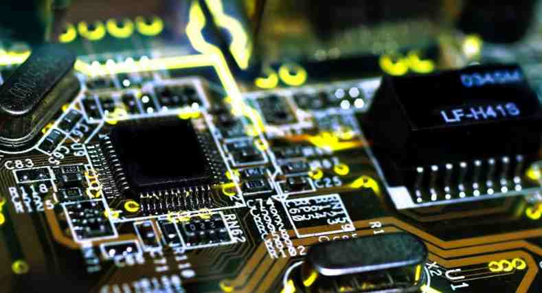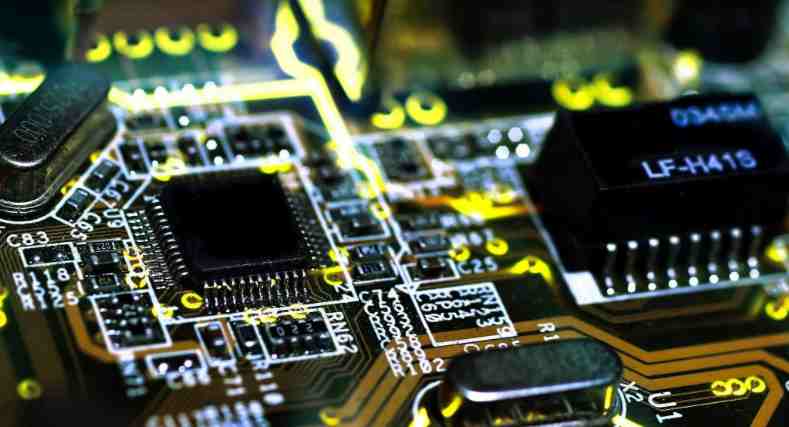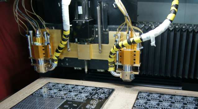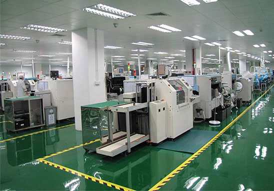
Since most of the invisible fine dust (dust less than 0.1mm in diameter) and a small amount of visible dust (dust greater than or equal to 0.1mm in diameter) have been removed during the process of panel splitting, the dust remaining on the product after panel splitting is mostly heavy dust with large particles.
2.1 The principle of dust removal is to "dust up" (the airflow speed required by industrial dust to dust up ≥20mm/s) and then "dust out";
2.2 The process window of vacuuming is relatively narrow for large particles of dust. When the vacuum suction port is farther away from the dust, the airflow speed drops more obviously, and the efficiency of vacuuming decreases faster. At a distance equal to the diameter of the pipe, the air velocity drops to only 7.5% of the air velocity in the suction pipe. However, the closer to the product, the higher the possibility of damage to the components caused by the vacuum suction port, especially for some high components (such as aluminum electrolytic capacitors). The high airflow speed may cause the product to be sucked up and scrapped, and the price of vacuuming equipment will also be greatly increased. In addition, as the complexity of product components increases, it is possible that when the vacuuming conditions of high components are met, other components cannot be met, that is to say, in this case, the pure vacuuming method is no longer feasible. Considering the HSE explosion-proof and environmental emission requirements of the factory, high-configuration vacuum cleaners are not cheap, such as the mainstream European explosion-proof vacuum cleaners with a price of 3kW can reach 80,000 to 150,000 RMB. If the pursuit of better negative pressure or flow, the price is amazing. So pure rely on vacuum cleaner to improve the performance, low cost performance is also a problem that has to be considered.

2.3 Due to the technological limitations of pure air dust removal, the method of blowing up dust with compressed air and then vacuums dust removal has become a commonly used method in the industry. The advantages of compressed air over pure air vacuuming are as follows:
high efficiency of dust removal:
process operability is strong;
process easier to control: air easy to adjust, easy to control airflow Angle and position;
compressed air is commonly used electronics factory configuration, easy materials;
equipment technical difficulty is low, design feasibility is strong;
equipment can use the standard parts on the market
equipment system is relatively simple, easy to design
maintenance is convenient;
the cost is low;
environmental
3. Key control point of process dust removal after dividing plate
3.1 Analysis of fishbone diagram
3.2 Principle of dust removal in process after subdivision
Four, after the board dust removal process management measures
4.1. Standardized workshop environmental management
Appropriate temperature and humidity not only affect the function of electronic components, but also have a certain impact on dust.
1) Appropriate temperature: 22~28℃.
Too low temperature dust is not easy to remove, too high temperature will affect the service life of the gas pipe, dust pipe.
2) Appropriate humidity: 30%RH~70%RH;
Too low humidity is easy to produce static electricity, too high humidity will cause dust viscosity increase difficult to remove.
4.2. Formulate process dust removal measures after sub-board
1) How to clean the dust on the circuit board - use compressed air to "dust"
Recommended measures are:
1.1) Air source design
1.1.1) Use an independent air source;
1.1.2) The air pipe inside the equipment should also be used independently without shunt;
1.1.3) Select the compressed air hose with appropriate pipe diameter through experiment. The outer diameter of the compressed air hose is within 10mm~16mm according to experience. Considering the layout of the gas pipe in the line slot and equipment and the possible movement of the gas pipe with the components, the softer material is better.
1.1.4) If necessary, air storage tanks can be used to reduce the pressure or flow loss of compressed air during work.
The field situation is more complex, the compressed air hose with too thick diameter is relatively hard, and it is difficult to turn and arrange in the layout of the equipment, which needs to be considered in the design and application. At the same time, it will affect the normal use of other station equipment on the bridge of the same facility, especially those sensitive to compressed air flow and pressure. In addition, it will also cause excessive gas consumption and increase costs. However, the compressed air hose with too small diameter also causes the rapid decline of air flow and pressure when blowing dust, so it is recommended that the specific diameter of the compressed air hose should be subject to the experimental data.
1.2) Jet head design
1.2.1) Considering the impact of static electricity generated by the high-speed flowing gas in the dust removal chamber on the electrostatic sensitive elements on the circuit board, the ion fan should be added;
1.2.2) Generally, the rotary jet meter is used to increase the coverage area of blowing air, and the rotating jet can
1.2.3) Increase the impact of gas on dust to facilitate dust generation. There are standard rotary blowers on the market such as Dr.Escherich's Taifun-Clean series. You can choose the ESD version of the rotary blowers directly so that you don't have to buy the ion blower separately.
1.2.4) The rotating air injection head should be as close to the circuit board components as possible to increase the efficiency of air blowing. It is recommended to be about 25mm~50mm away from the highest components, depending on the characteristics of components and the design of WPC.
1.2.5) The general circuit board is placed on the WPC(Work Piece Carrier carrier) to facilitate the handling of different products. If you can, you can use a non-clip-on WPC (that is, the circuit board is placed directly on the WPC), which will make the structure of the device simpler, and because the circuit board contact part is less so that the shadow area when cleaning is less, the cleaning effect is good.
1.2.6) The rotary jet heads are generally a pair, respectively mounted on both sides of the circuit board. Generally the back of the circuit board (that is, the auxiliary surface of the circuit board) of the rotary air jet relative to the front of the circuit board (that is, the main surface of the circuit board) to stay away from the circuit board (such as can be appropriate to stay away from about 11mm), so that it is not easy to blow off the WPC or the circuit board on the WPC when working. At the same time, because the dust on the back of the circuit board is less, the air pressure of the rotating jet head can be relatively small, depending on the situation.
1.2.7) Layout of the air pipe: the shorter the length, the better, and the fewer turns, the better, to reduce the loss of air flow.
2) How to discharge the dust in the dust removal chamber in time - "dust removal"
2.1) The dust removal chamber should be designed as small as possible to improve the dust removal efficiency;
2.2) Dust removal chamber design should try to avoid dust dead Angle;
2.3) Under the dust removal chamber to make a cone, and the steeper the better, recommended and horizontal Angle ≥60° (commonly used Angle of 60° and 75°, to facilitate manufacturing), at the same time the cone inner surface as flat as possible.
2.4) The suction port of the dust removal chamber is located at the top corner of the cone, and the larger the diameter of the vacuum cleaner, the better. For details, we can discuss with the vacuum cleaner supplier. For example, the diameter of the vacuum cleaner's vacuum port is Ø70. If there is one vacuum port, the diameter is still Ø70; if there are two vacuum ports, the diameter of each vacuum port is Ø50. Note: The diameter of the suction port of the general dust removal chamber should not be larger than the diameter of the connected vacuum cleaner.
dusting mouth cavity vacuuming generally and rotating coaxial jet head, on the same side, this can maximize the efficiency of dust collection.
relatively separate vacuuming, recommend the use of large surface to the depth of the dust cover.
2.5) As for vacuum cleaners, it is suggested to choose suitable vacuum cleaners together with vacuum cleaner suppliers. Since the dust is generated by compressed air, it is not necessary to configure a vacuum cleaner with a high vacuum degree, but a vacuum cleaner with a high air flow rate should be configured in order to remove the dust raised by compressed air in time.
2.6) Reasonable layout of dust pipe, strive to use the shortest dust pipe, try to make dust with gravity downward suction by the vacuum cleaner, try to avoid or reduce anti-gravity dust suction upward.
3) How to reduce quality problems, downtime and maintenance costs caused by equipment -- "lean" equipment design
3.1) Product fixation is best done by the rational design of the equipment, do not use additional fixing parts to prevent the product from falling off the WPC or out of position. The way of belt driving WPC is safer than that of cylinder driving WPC in the dust removal chamber, in addition, avoid or reduce the WPC staying in the dust removal chamber. The dust removal time can be controlled by changing the belt speed or multiple rotating jet heads to ensure the dust removal effect. In addition, the dust removal chamber body should try to avoid the cylinder (including horizontal load cylinder and up and down lifting cylinder), if necessary can put WPC
The waiting area and related cylinders are set outside the dust removal area.
3.2) Preference is given to market standard parts, such as Taifun-Clean units by Dr.Escherich
3.3) If the impact of noise on the environment or operator is considered, a closed or relatively closed chamber shall be used.
3.4) Photoelectric components (such as photoelectric sensors, etc.), bearings, cylinders, etc. should be avoided in the dust removal chamber.
V. Conclusion
It is recommended to use a relatively closed dust removal chamber for dust removal after the separation process. The smaller the volume of the chamber, the better. Use rotary compressed air blowing (if there is water and impurities in the air source in the factory, use three pieces of filter) to blow up the dust on the circuit board, and then use a vacuum cleaner to suck the dust away. In consideration of anti-static, the general use of compressed air blowing + rod type static eliminator to achieve. Set the dust removal chamber reasonably, select the right rotary blower and vacuum cleaner, and arrange the compressed air hose and vacuum hose reasonably. Buying Dr.Escherich's Taifun-Clean system and integrating it into an automated track or device is also a good option.
During design, WPC can be designed according to product characteristics to reduce shadow areas and avoid collision parts.


