What is radio frequency circuit?
Radio frequency is short for RF, radio frequency is RF current, it is a kind of high-frequency alternating change electromagnetic wave short for. An alternating current that varies less than 1,000 times per second is called a low frequency current, and one that varies more than 1,000 times per second is called a high frequency current, and radio frequency is such a high frequency current.
An RF circuit is one in which the electromagnetic wave length of the signal processed is of the same order of magnitude as the size of the circuit or device. At this time, due to the relationship between the size of the device and the size of the wire, the circuit needs to be treated with the relevant theory of distributed parameters. All such circuits can be considered as radio frequency circuits, and there is no strict requirement on their frequency. For example, AC transmission lines with long distance transmission (50 or 60Hz) sometimes need to be treated with the relevant theory of RF.
Two, the principle and development of radio frequency circuit

The most important application field of RF circuit is wireless communication. Figure 1.1 is a block diagram of a typical wireless communication system. The following takes this system as an example to analyze the role of RF circuit in the whole wireless communication system.
This is a wireless communication transceiver (tranceiver) system model, it contains the transmitter circuit, receiver circuit and communication antenna. The transceiver can be used in personal communication and wireless local area networks. In this system, the digital processing part is mainly to process the digital signal, including sampling, compression, coding and so on. The converter then passes through A/D converter into an analog form into an analog signal circuit unit.
The analog signal circuit is divided into two parts: transmitting part and receiving part. The main function of the transmitting part is: the low-frequency analog signal output from digital-to-analog conversion and the high-frequency carrier provided by the local oscillator are converted into an RF modulation signal through the mixer, and the RF signal is radiated into the space through the antenna. The main function of the receiving part is: the space radiation signal is coupled to the receiving circuit through the antenna, and the weak signal received is amplified by the low noise amplifier and the local oscillation signal is converted down to the signal containing the IF signal component through the mixer. The function of the filter is to filter out the useful IF signal and then convert it into a digital signal by the input analog-digital converter, and then enter the digital processing part for processing.
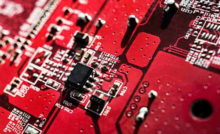
Next, the composition and characteristics of general RF circuits are discussed with regard to the low noise amplifier (LNA) in the block diagram in Figure 1.1. Figure 1.2 shows a circuit board diagram of this amplifier using Tri Quint's TGA4506-SM as an example, noting that the input signal is fed into the amplifier module through a network of matched filters. The amplifier module generally adopts the common emitter structure of the transistor, whose input impedance must be matched with the output impedance of the filter located in front of the low noise amplifier, so as to ensure the best transmission power and minimum reflection coefficient, for RF circuit design, this matching is a must. In addition, the output impedance of the low noise amplifier must match the input impedance of the mixer at the back end, also to ensure that the amplifier output signal can be fully, non-reflective input into the mixer. These matching networks are composed of microstrip lines and may sometimes be composed of independent passive devices, but their electrical characteristics at high frequencies are completely different from those at low frequencies. It can also be seen from the figure that the microstrip lines are actually copper coated strips of a certain length and width, and connected with the microstrip lines are sheet resistors, capacitors and inductors.
In electronics theory, an electric current flows through a conductor and a magnetic field forms around it. Alternating current passes through a conductor, and an alternating electromagnetic field, called electromagnetic wave, is formed around the conductor.
When the electromagnetic wave frequency is lower than 100khz, the electromagnetic wave will be absorbed by the surface and cannot form effective transmission. However, when the electromagnetic wave frequency is higher than 100khz, the electromagnetic wave can propagate in the air and be reflected by the ionosphere at the outer edge of the atmosphere, forming the long-distance transmission capability. We call the high-frequency electromagnetic wave with the long-distance transmission capability as radio frequency, English abbreviation: RF.
High frequency circuit is basically composed of passive component, active component and passive network. The frequency characteristics of components used in high frequency circuits are different from those used in low frequency circuits. The passive linear components in high frequency circuit are mainly resistors, capacitors and inductors.
In the field of electronic technology, the characteristics of RF circuits are different from those of ordinary low-frequency circuits. The main reason is that under high frequency conditions, the circuit characteristics are different from that under low frequency conditions, so it is necessary to use the RF circuit theory to understand the working principle of the RF circuit. Under high frequency conditions, stray capacitance and stray inductance have great influence on the circuit. Stray inductors exist in the internal self-inductance of wire connections and components themselves. Stray capacitors exist between conductors of a circuit and between components and ground. In low-frequency circuits, these spurious parameters have little effect on the performance of the circuit, and the influence of spurious parameters becomes greater and greater with the increase of frequency. In the high frequency heads of early VHF television receivers, as well as the front-end circuits of communication receivers, the effect of stray capacitance is so great that additional capacitance is no longer necessary.


