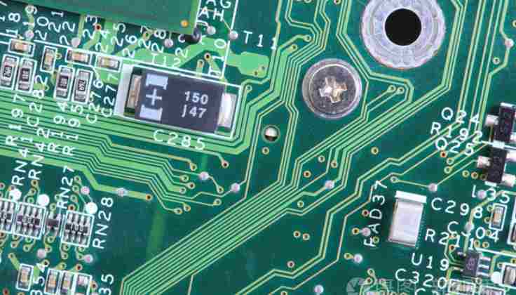
1. Heat dissipation through PCB board itself: at present, PCB board is widely used in copper/epoxy glass cloth substrate or phenolic resin glass cloth substrate, and a small amount of paper-based copper coated plate. Although these substrates have excellent electrical properties and processing properties, but poor heat dissipation, as a heat dissipation way of high heating components, almost can not be expected from the PCB resin conduction heat, but from the surface of the components to the surrounding air heat dissipation. However, as electronic products have entered the era of component miniaturization, high-density installation and high thermal assembly, it is not enough to only rely on the surface of components with very small surface area to dissipate heat. At the same time, due to the large number of surface mounted components such as QFP, BGA, the heat generated by components to PCB board, therefore, the best way to solve the heat dissipation is to improve the heat dissipation capacity of PCB aluminum substrate in direct contact with the heating element, through the PCB board to conduct out or send out.
2. For equipment with free convection air cooling, it is best to arrange integrated circuits (or other devices) by length or by transverse length.
3. Use reasonable wire design to achieve heat dissipation: because the resin in the plate has poor thermal conductivity, and the copper foil line and hole are good conductors of heat, so improving the copper foil residual rate and increasing the heat conduction hole is the main means of heat dissipation.
4. High heating device with radiator, heat conduction plate: when the heat of a few components in PCB is larger (less than 3), can be added on the heating device radiator or heat conduction tube, when the temperature can not fall, can be used with a fan radiator, in order to enhance the heat dissipation effect. When the amount of heating devices is large (more than 3), you can use a large heat sink (plate), which is customized according to the position and height of the heating devices on the PCB board, or in a large flat radiator cut out different positions of the components. The radiator cover is fastened on the component surface as a whole, and contact with each component to dissipate heat. However, due to the low consistency of components during welding, the heat dissipation effect is not good. Soft thermal phase change pads are usually added on the surface of components to improve the heat dissipation effect.

1. Making negatives: Due to the existence of side corrosion, the drawing line accuracy must be equal, so certain process compensation must be made in the light drawing negatives, and the process compensation value must be determined according to the measurement of the side corrosion value of different thickness of Cu. The negative is negative.
2. Material preparation: try to purchase 300×300mm fixed size plates with protective film on Al and Cu surfaces, and the dielectric constant is the same as the drawing.
3, the graphics: Cu surface treatment with chemical corrosion treatment is recommended, the best effect. Cu surface treatment, drying immediately after wet screen printing film, to prevent oxidation. After development, use the scale magnifying glass to measure whether the line width and gap meet the requirements of the drawing, to ensure smooth lines without jagging. If the thickness of the UFO aluminum substrate is greater than 4mm, it is recommended to remove the driving roller of the developing machine to prevent the plate from causing rework.
4, etching: acid CuCl-HCl solution corrosion. The solution was adjusted with the test plate to etch the Al substrate when the etching effect was optimal, and the figure was placed face down to reduce the amount of side erosion.
5, surface treatment (immersion Sn) : after the completion of the etching process, do not rush to remove the film, immediately prepare the immersion Sn solution, that is, the film, that is, the immersion Sn, the best effect.
6, machine: shape processing, should use numerical control milling machine, PTFE and aluminum substrate part separate processing, so as to avoid the stratification phenomenon caused by the different thermal conductivity and deformation of the two, should also be graphics face up, in order to reduce stratification and burr.
The most obvious characteristic of the electronics industry is ceaseless change, and the technology of the electronics industry will never cease. In our daily life, contact with aluminum based materials of high technology is always the first electronic products. Electronic products are being replaced very quickly. LED technology, now can not be the latest technology, but still in people's brainstorming, feel the changes brought by the new technology.
In LED lighting technology, has a very important role, namely the application of aluminum substrate. The application of aluminum-based materials is very special. On either side of the aluminum substrate, one side is the current loop forming the LED, which requires a very delicate process. On the other hand, aluminum substrate is a very important aspect to form a more stable cooling system. Aluminum substrate materials and other outstanding advantages, as a substrate, copper and iron substrate can be considered material, but relatively speaking, or choose aluminum substrate, aluminum substrate material has better plasticity, but also has better heat dissipation, very suitable for at the same time, the material cost is not too high. Because the aluminum base material has excellent cooling effect, the heat dissipation in the circuit process is evaporated in time, prolong the service life of components, so that the circuit is more stable and durable.


