PCB milling machine, processing type and PCB layer connection mode
PCB manufacturers, PCB designers and PCBA manufacturers will explain PCB milling machines, processing types and PCB layer connection methods
1. Milling machine
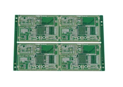
In the process of milling circuit boards, both very complex shapes, such as straight lines, oblique lines, arcs, and circles, can be completed by milling, and the machined surfaces with higher dimensional accuracy and smoothness can be obtained than those by cutting, punching, and cutting. CNC milling machine or milling mechanical device is usually used. It has the following characteristics:
(1) High precision position structure: the same structure as the CNC drilling machine, each axis of X-Y-Z axis operates independently;
(2) High rigidity high-speed spindle: 7000-40000 (rpm), the spindle adopts ball bearing;
(3) Hole identification function: it can accurately detect the thickness of the substrate surface and ensure the depth accuracy
(4) Flexible commands of various types (such as cutting, feed speed, tool lowering and tool lifting);
(5) With automatic compensation function: NC milling is programmed according to the actual dimensions of PCB. At the same time, the coordinate of milling cutter movement is the centerline. In this way, the movement track of the milling cutter should reduce one milling cutter diameter for the overall dimension; For the internal figure, it is to increase the size of a milling cutter diameter. According to this principle, the automatic compensation function can automatically shift the input milling cutter diameter by a radius to achieve the purpose of correction.

2. Type of processing
(1) Profile processing: 0.8-3.175mm, groove processing
(2) Hole drilling: The holes drilled are mainly used to fill IC chips, and the depth accuracy is required to be less than 50um.
3. Type of milling cutter
The milling cutter used for PCB contour processing is usually made of cemented carbide, which can be divided into spiral teeth and diamond teeth according to the tooth shape.
(1) Helical milling cutter
This kind of knife is characterized by small front angle, large rear angle and backhoe. This structure makes the cutting edge strong and sharp.
(2) Rhombic tooth milling cutter
On the cylindrical surface of the milling cutter, a number of left and right chip discharge grooves with different numbers are processed, forming a staggered diamond. Produce small, flat cutters on each diamond. The cutting tool is on the left spiral, suitable for low speed cutting; The cutting edge is on the right screw, suitable for high-speed cutting.
Connection mode between PCB layers
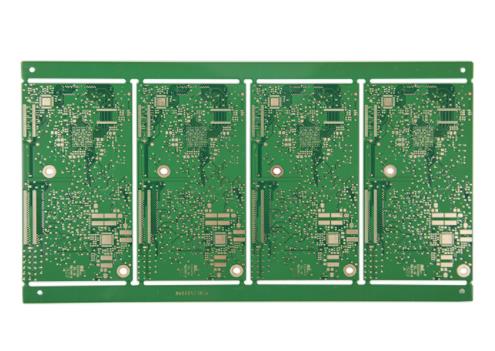
According to the classification of circuit boards, circuit boards can be divided into single-sided, double-sided, multi-layer and other different structures according to the number of layers of metal circuits. The practice of multilayer board can be divided into traditional pressing method and layer adding method. The traditional method of multilayer board is to first make the inner board circuit, check the circuit integrity and confirm the yield, and then send it to the pressing room for multilayer board pressing. For example, when making an eight layer board, three inner layers should be made first, which should be combined with the black browning treatment, and then the processed three inner layers plus the stacking film should be pressed with the upper and lower copper sheets. After the pressing is completed, it is the so-called eight layer board structure. However, in order to connect to the interlayer conduction, it must be combined with the drilling and hole wall metallization process in order to have the signal or electric conduction.
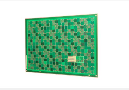
For multilayer boards made by layer adding method, the manufacturing method is to build a core hard board in the center, and on this basis, do the growth layer adding operation to both sides. This is the 1+4+1, 2+4+2 and other multilayer boards in the general channel. Each layer adding in this method includes the procedures of black browning, layer adding pressing, blind through hole making, hole wall metallization and circuit making. The added layers of structure go through several process cycles, Therefore, the yield requirement of each layer is more stringent than that of traditional multilayer boards. This kind of board is also known as high-density interconnection board, which is also known as HDI board.
In addition to conducting HDI boards by laser tapping and electroplating, circuit board manufacturers also have other methods to conduct interlayer conduction treatment, such as conductive glue hole technology, which uses conductive glue to fill holes and connect them to the conduction effect, such as ALIVH and B2it in Japan. Other special methods include Manhattan technology. First, the conducting copper column is made, and then the copper skin is pressed through by pressing method to connect to the conducting. These methods do not require the hole wall metallization process. PCB manufacturers, PCB designers and PCBA processors will explain PCB milling machines, processing types and PCB layer connection methods.


