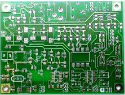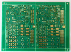
PCB bare wire testing process is indispensable. With the development of science and technology, you may think that simple testing equipment based on bare wire (refers to two or more wires with load power and/or low speed signal in a sheath) is going out of date. A sample survey on the cabling installation industry shows that the bare wire installation business is likely to grow under the condition that distributed audio, security, room control and automatic operating systems are more widely used.
Bare wire test -- to verify end-to-end connectivity
Connectivity test is one of the most basic test items of bare wire test, which is used to search the continuous path through each PCB wire. For connectivity testing, you can use a resistance based multimeter to short the ends of the wires to ensure a complete loop. When connecting PCB devices such as speakers, you may need to test the resistance coefficient. When connecting the safety device, you may want to test the switching condition of the switch. When checking the switching condition, it is usually supplemented by a sound indication of the closed circuit. Many multimeters, such as Fluke multimeters, have this function. This basic test can also be completed by many current inductive audio generators, such as MicroNetBlink? Of Fluke Network This audio generator is equipped with a simple LED display, which makes general connectivity testing easy.

Bare wire test -- polarity test
Similar to the connectivity test is the polarity test. Usually, a multimeter is used for polarity test, but an inductive audio generator with this function can also easily complete the test. MicroNetBlink of Fluke Network can clearly display the polarity through color LED lights. Generally, low-voltage polarity test is mainly used for power or signal lines of telephone cables and security monitoring cameras.
Bare wire test -- length measurement
The distance to the short circuit or open circuit point is an important information for fault detection, and it is also an important information for material management and installers to calculate charges. Length can be measured electronically in three ways. The first method is to short the two wires together, then measure the resistance and convert the measured value into length. Unfortunately, this method requires a short cable and is rarely used.
You can also measure the length by capacitance. Just like resistance, the capacitance between two wires will vary with the length. The advantage of measuring the length by capacitance is that you do not need to short the two wires together. The 620 LAN cable tester, NetTool network multimeter, LinkRunner Link Connect and other products of Fluke Networks can use capacitance to measure the cable length.
The third method is to use time domain reflection (TDR) technology, which is similar to testing copper wire with an electric wave detector. Send the electric wave down to the cable, and the electric wave will be reflected back when encountering open circuit or short circuit between wires. The length of the cable can be obtained by recording the time when the radio wave is sent back.
The transmission time varies with the propagation rate constant of different types of cables. This constant is usually marked on the cable box, but the TDR of the cable reference length can also be used to calculate the constant with reasonable accuracy. MicroScannerPro cable tester, DSP-4300 and OMNIscanner 2 digital cable analyzer all have TDR function.
Bare wire test -- fault detection and material management
The basic management of the use of raw materials is a daily task. At the beginning of each working day, the length of the cable in the box or spool to be used should be checked. If a TDR or capacitive tester is used, there is no need to short the cable ends. Make a note of the value and make sure it is long enough for your cable. At the end of a day's work, the length of the cable in the box or on the spool should be checked again. The length measured this time should be subtracted from the number measured before the work starts to get the length of the cable used in the day.
Another example of length testing is failure detection before work is completed. If you are using TDR for wiring connectivity testing, you suddenly find a short circuit 10 meters away, but in your records, the link should be 50 meters long. It may be that the dry wall installer just nailed the nail at a certain point, and you may be able to find the location of the short circuit and repair it (the twisted pair is different, and you need to replace the cable).
Bare wire test -- use audio generator and probe to locate cable fault
How can you find the nail point on the cable? Does your TDR show it's ten feet away? You can use an inductive audio generator and probe such as MicroNetBlinkKit of Fluke Network to test. Connect the audio generator to two wires and power them on. The cable will send a signal through the dry masonry wall. Then use the MicroProbe audio probe of Fluke Network to capture the 1000 Hz signal and convert it into audio signal to quickly find the fault point.
Catching such a signal is both good and bad for your work. You can use this signal to detect the PCB wire in the wall, but if you encounter two parallel cables, you may encounter trouble. One of the non powered cables may capture the signal of the powered cable, making it difficult to identify them. To avoid this trouble, a certain distance shall be reserved between the two bare wires when wiring. In addition, the cable will collect the noise from the fluorescent lamp or the running machine. In order to ensure the speed of line checking, these noises should be minimized.
The bare wire test method is introduced. For your work, their significance is not only in simple connectivity testing, but also can help you reduce the time for fault detection and handling. I hope readers can master PCB industry knowledge.


