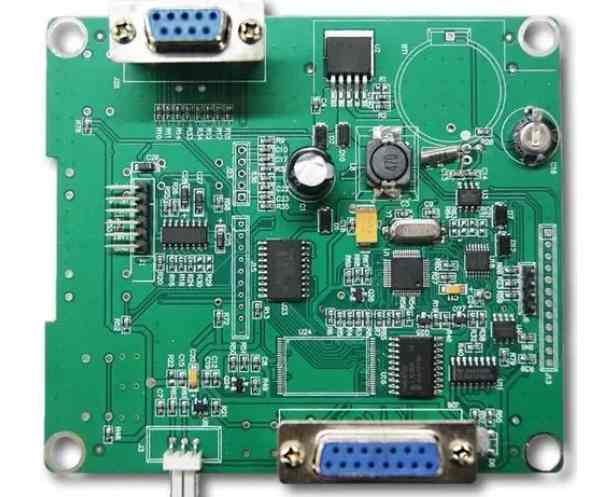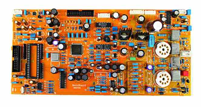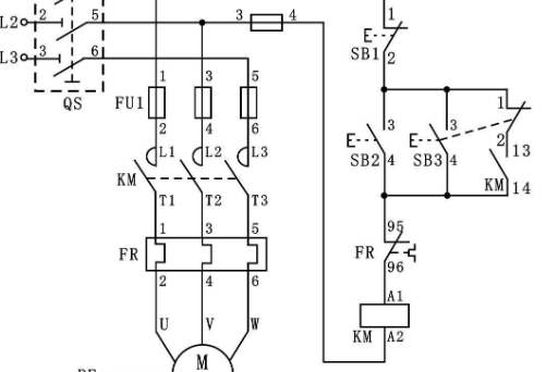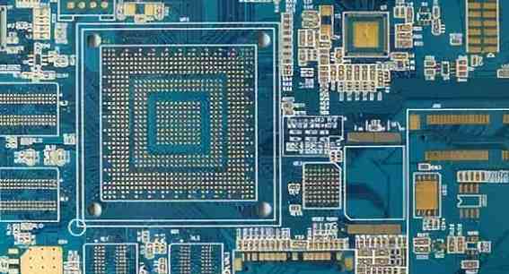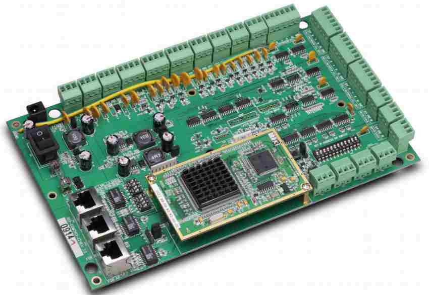
Check the situation of the pressure tank camera according to the design scheme construction and alarm content, and according to the electrical schematic diagram. Printed pcb circuit board is the initial application of paper - based copper-coated circuit board. Since the appearance of transistor in the 50's of the 20th century, the demand for circuit boards has increased significantly. The following patch processing manufacturers to explain how to check the circuit board and how to improve the efficiency of SMT patch related knowledge.
1. How to improve SMT patch processing efficiency
(1) As far as possible, when the mounting head picks up electronic devices, the same type of electronic devices will be lined up together, so as to reduce the number of changing the nozzle when the mounting head picks up electronic devices, and save the patch time. The feeder with more times of pick up should be placed in the feeder near the PCB board. During the entire process of picking up the respiratory system, try to only stand on the feeding from the back or back of the material to reduce the distance between mounting head movements. During the entire process of each pick up respiratory system, the mounting head is prompted to overload. Some specifications are contradictory in the context of improved operating procedures, which must be given the best possible consideration in order to screen out good improvements.
The system can be improved when load distribution and mechanical equipment improvement are carried out. The software optimization includes the improvement of the operating procedure of mechanical equipment and the mobile phone app for the balance of the production line. The improvement of the operation procedure of the mechanical equipment is mainly aimed at the patch operation procedure and the configuration of the feeder. After obtaining BOM and CAD data information of electronic components, it can be converted into piece-type operating program and feeder configuration table. Improving the operation program will improve the relative path of exercise and fitness of the mounting head and the configuration of the feeding and feeder, minimize the moving distance of the mounting head, and thus save the piece-type time. Production line balancing mobile phone app is an effective and common tool to improve all automatic production lines. Software optimization uses a certain way of lifting calculation. The current software optimization has long been intelligent, which can quickly and well carry out the improvement of the whole process.
(2) SMT automatic production line is composed of several mechanical equipment, including screen printing machine, SMT placing machine, reflow furnace, but in fact the speed of the automatic production line is managed by the SMT placing machine. An automatic SMT production line generally consists of a high-speed machine and a precision machining SMT placing machine, with an important chip type small electronic device at the front and an important chip type IC and special-shaped electronic device at the back. When the two SMT SMT machines take the same and small time to carry out the entire SMT SMT process (hereinafter referred to as the SMT SMT time), the total output of an automatic SMT production line will be fully utilized.
In order to ensure this guideline, we can treat the patch operation program in the following way. Load distribution is balanced. Reasonable allocation of the number of piece-type electronic devices for each mechanical equipment, as far as possible to make the piece-type time of each mechanical equipment the same. When we initially allocate the number of piece-type electronic devices for each mechanical equipment, there will generally be a big difference in piece-type time, so it is necessary to adjust the production and processing load of all mechanical equipment in the automatic production line according to the piece-type time of each mechanical equipment, and move part of the electronic devices on the mechanical equipment with a long piece-type time to another mechanical equipment. To balance the load distribution. Mechanical equipment is improved. Each SMT machine has a large SMT speed value, such as YAMAHA's YV100 called 0.25 seconds per piece, but in practice this speed value has to be done under certain specifications. To improve the operation procedure of CNC lathes for each mechanical equipment is to make SMT SMT machines conform to such specifications as much as possible in the production process, so as to carry out high speed SMT and reduce the time of mechanical equipment. Improved specifications depend on the construction of the mechanical equipment. For X/Y structure SMT machine, generally according to the following specifications to improve.

2. How do I check the circuit board
Circuit board test: the failure test and analysis of the drug granules: this system has two pressure tanks, one at the top and one at the bottom, and the middle is separated by the pneumatic cut-off valve. The pressure tank is equipped with two cameras, one at the top of the clay pot and one at the bottom of the pot, which are used to check the position of the steel wide-angle lens of the high pressure vessel. The camera is put into the tank for accurate measurement and the amplifier circuit in the pressure tank. Check the situation of the pressure tank camera according to the design scheme construction and alarm content, and according to the electrical schematic diagram. Printed pcb circuit board is the initial application of paper - based copper-coated circuit board. Since the appearance of transistor in the 50's of the 20th century, the demand for circuit boards has increased significantly.
Very is the rapid development trend of integrated circuit chips and widely used, so that the volume of electronic products is smaller and smaller, the power circuit line relative density and difficulty coefficient is more and more large, which provides that the circuit board to continue to innovate. At present, the types of circuit boards have developed from single-sided aluminum substrate to double-sided circuit boards, solid wood multilayer boards and flexible boards. Structure and quality have also developed to the level of extremely high relative density, miniaturization and sales price; New design scheme, design scheme equipment and raw materials, board processing technology emerge endlessly. In recent years, a variety of CAD printed pcb circuit board system software has been popularized and promoted in the manufacturing industry, in the finely differentiated circuit board manufacturers, professional, automatic technology manufacturing has been completely replaced by manual production.
3.How to prevent smt patch machining defects
Some details of SMT patch processing can eliminate unnecessary situations such as incorrect solder paste printing and solder paste removal from the board. Our goal is to deposit the solder paste in the desired location. Misalignment of dye tools, dry solder paste, stencil and circuit board can result in unwanted solder paste on the bottom of the stencil or even during assembly.
Common paste problems: Can you scrape the wrong paste off the board with a small scraper? Does this cause solder paste and small solder joints to enter pores and small gaps?
Using a small scraper to remove solder paste from a misprinted circuit board can cause problems. Misprinted plates can usually be soaked in compatible solvents, such as aqueous additives, and small tin particles can be removed from the plate with a soft brush. I prefer soaking and cleaning over and over again, rather than forcing dry brushes or shovels. After the solder paste is printed, the longer the operator waits for the printing error to be removed, the more difficult it will be to remove the solder paste. When a problem is found, improperly printed plates should be immediately placed in a soaking solvent, as the solder paste is easily removed before drying.
Wipe with a rag to avoid solder paste and other contaminants on the board surface. After soaking, cleaning with a mild spray usually helps to remove unnecessary cans. At the same time, the patch factory also recommends hot air drying. If using a horizontal shape cleaner, the cleaning side should be down to remove the solder paste from the plate.
3. SMT chip processing to prevent solder paste defects:
During the printing process, there is a specific pattern of template erasure between printing cycles. Ensure that the stencil is on the pad and not the solder mask to ensure that the solder paste printing process is clean. On-line, real-time slurry inspection and reflow welding are process steps to reduce pre-welding defects.
For miniature stenciling, if there is damage between the fine needles due to bending of the stencil parts, the solder paste between the needles may be deposited, resulting in printing defects and/or short circuits. Low viscosity can also lead to solder paste printing defects. For example, high operating temperatures or high speed blades can reduce the viscosity of solder paste during use, leading to printing defects and electric Bridges leading to excessive deposition of solder paste.


