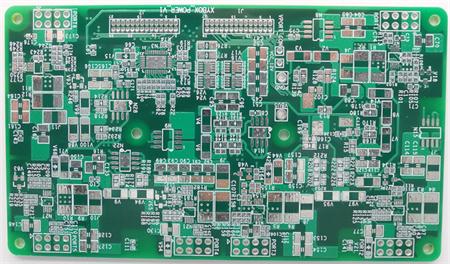
In the early days, it was used to weld and assemble circuit boards of various circuits, so it was called printed circuit board. printed circuit board, also known as PCB and printed circuit board, is the provider of electrical connection of electronic components.

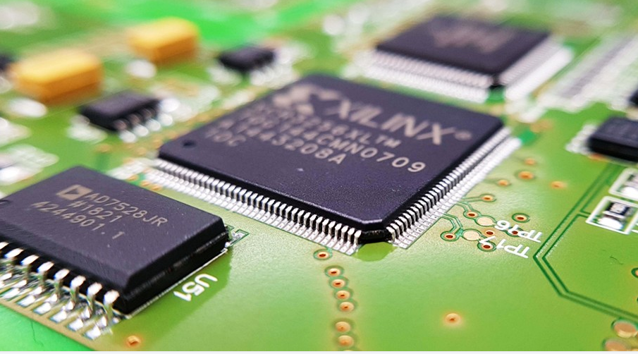
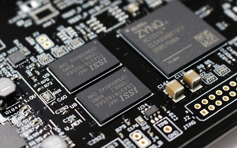
According to the number of circuit board layers, it can be divided into single panel, double panel, four layer board, six layer board and other multi-layer circuit boards. As PCB is not a general terminal product, the definition of its name is slightly confused. For example, the motherboard for personal computers is called the motherboard, but not the circuit board. Although there are circuit boards in the motherboard, they are not the same. Therefore, when evaluating the industry, they cannot be said to be the same. Another example: because there are integrated circuit parts loaded on the circuit board, the news media call it IC board, but in fact it is not the same as printed circuit board. The printed circuit board we usually refer to the bare board - that is, the circuit board without upper element devices.
Before the appearance of printed circuit board, the interconnection between electronic components depended on the direct connection of wires to form a complete circuit. In the contemporary era, the circuit board only exists as an effective experimental tool, while the printed circuit board has become the absolute dominant position in the electronic industry.
At the beginning of the 20th century, in order to simplify the production of electronic machines, reduce the wiring between electronic parts, reduce production costs and other advantages, people began to study the method of replacing wiring with printing. Over the past three decades, engineers have repeatedly proposed to add metal conductors to insulated substrates for wiring. The most successful was that in 1925, Charles Ducas of the United States printed the line pattern on the insulating substrate, and then successfully established the conductor as the wiring by electroplating.
Until 1936, Paul Eisler, an Austrian, published foil technology in Britain. He used printed circuit boards in a radio device; In Japan, Yoshisuke Miyamoto successfully applied for a patent by using the spray wiring method. In both cases, Paul Eisler's method is the most similar to today's printed circuit boards. This kind of method is called subtraction method, which is to remove unnecessary metals; Charles Ducas and Yoshisuke Miyamoto only add the necessary wiring, which is called the addition method. However, due to the high heat generated by the electronic parts at that time, the substrates of the two were difficult to be used together, so there was no formal practical use. However, the printed circuit technology was further developed.


