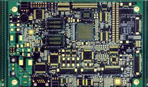
Holes and cracks between holes, shape swelling, waste jumping and waste plugging.
1, burr
cause
Concave and punch clearance is too small, resulting in cracks on both sides of the punch and die without coincidence, two extrusion shear occurs at both ends of the section.
The gap between concave and punch is too large. When the punch drops, the crack occurs late, and the shear is completed like tearing, causing the crack to not coincide.
Edge wear or the appearance of fillet and chamfering, cutting edge does not play the role of wedge segmentation, the entire section produces irregular tearing.
solution
Reasonable choice of concave and punch blanking clearance. Such punch cutting is between extrusion and tension. When the punch cuts into the material, the cutting edge forms a wedge, causing the plate to produce a nearly linear coincidence crack.
Timely trim the fillet or chamfer produced by the edge of concave and punch die.
Ensure the vertical concentricity of the concave and punch, so that the fit clearance is uniform.
Ensure mold installation is vertical and smooth.
2, copper foil face around the mouth bulge
cause
Concave, punch punching clearance is too small, and punch edge blunted. When the punch is pushed into a preheated and softened printed board, the plate moves outward and upward around the punch.
The punch edge has a taper. As the punch continues to enter the plate, the bulge around the orifice will increase as the punch taper increases.
solution
Blanking should exceed 20 percent of the original design thickness; Otherwise replace the plate or redesign the die.
Blanking should have enough pressing force to overcome the backsqueezing force of material movement when punching;

3, the orifice copper berth up
Cause:
Due to recoil, the copper foil is pulled into the blanking gap of the concave and punch.
The copper foil has a poor bond with the substrate. When the punch is pulled out of the printed board hole being punched, the copper foil is pulled upward with the punch.
The punch edge end has an inverted cone, bulging and deformation, when the punch is pulled out of the hole in the printed board, the copper foil is pulled upward with the punch
Solution:
Adopt forward impact.
Replace the punch.
The fit gap between punch and discharge plate should not be large, and sliding fit should be adopted.
4, the base surface around the orifice layer white
cause
Concave, punch punching clearance is not appropriate or concave mode edge blunted. When punching, it is difficult for the sheet to form shear cracks at the edge of the concave mode.
Substrate blanking performance is poor or not preheated before blanking.
Low compression force.
The material leakage hole under the cutting edge of the die is blocked or the material leakage resistance is large, resulting in expansion stratification.
Solution:
Reasonable expansion of concave, punch punching clearance;
Timely repair dull die cutting edge;
Increase the pressing force;
Adjust the preheating temperature of the substrate;
Enlarge or ream the leakage hole
5, hole wall tilt and deviation
cause
Punch rigidity is poor, centering instability, tilt into the workpiece.
The punch installation tilt or the clearance with the discharge plate is too large, the discharge plate can not play a precise guiding role on the punch;
The fit clearance of concave and punch is uneven. The side with small clearance, the punch radial force is large, sliding to the side with large clearance; 4). Concave and convex mode assembly concentricity difference; Push plate and concave, punch shape deviation; Poor matching accuracy of pusher plate and die (refers to compound blanking).
Solution:
Reasonable selection of punch materials; Improve punch rigidity, strength, hardness and unstraightness.
Improve the processing concentricity and assembly concentricity of punch and die.
Improve the fit precision of punch and discharge plate to ensure precise guidance.
Ensure the machining accuracy and assembly accuracy of guide column and guide sleeve; Reduce the fit gap between the shape of pusher plate and the die, and make the shape of pusher plate consistent with the concave and convex shape.
6, rough section
cause
The punching clearance of concave and punch is too large; The cutting edge of the die is badly worn.
The punching force of the punch is insufficient and unstable. 3). Sheet blanking performance is poor. For example, the substrate contains too much glue, substrate, aging, laminating bond is low.
solution
Select the appropriate dent and punch punching clearance.
Timely trim the cutting edge of the die.
Select the substrate with better blanking performance and control the preheating temperature and time strictly according to the process requirements;
7. Holes and cracks between holes
cause
The hole wall is too thin and the radial extrusion pressure during punching exceeds the strength of the hole wall of the printed board substrate.
The two holes near each other are not flushed out at the same time. When the punch enters the plate, the hole wall is too thin and will be cracked
solution
The hole spacing design on the printed board should be reasonable, and the hole wall should not be less than the thickness of the substrate.
Adjacent holes should be flushed out at the same time with a pair of molds.
The two adjacent punches are made into different lengths with a difference of 0.5mm, so that the concentrated blanking force within a small area is dispersed instantaneously.
8, the shape of bulge
cause
Mold design is not reasonable. For the larger size of the printed board, such as the use of the concave die without pushing the material plate falling material, the printed board is always bent to the concave mode hole in the case of self-weight. In addition, when the punch punch, the air flow to the workpiece has a shock wave, so that the center of the workpiece is more curved, and the downward bending near the edge of the concave die is very small, resulting in the shape of bulge.
The concave die of contour blanking is deformed, and the long edge is swollen.
solution
When the size of the printed board is greater than 200mm, it is appropriate to use the mold punching shape of the blanking structure. If the mold structure of falling material is used, it is necessary to install a pusher plate with elastic supporting force in the concave die, so that the printed board does not deformation.
Increase the wall thickness of the die, or choose materials with sufficient bending and tensile strength to make the die.
Reduce heat treatment deformation of die as much as possible. For the die with complex geometry, it can be hardened by selective heat treatment and then wire cutting to overcome the deformation.
9, scrap jumping
(Sometimes parts of the waste do not fall down when punching, but jump up; Some into the workpiece hole, but also need to manually remove; Some jump above the lower die, affecting the normal blanking work).
cause
Copper foil and substrate adhesion is poor, the copper foil on the scrap when punching is easy to fall off, with the punch out of the die, into the punching.
Die clearance is too large, and the leakage is not smooth, when the punch exits the die unloading, the waste will jump up. 3). Die hole has inverted cone, punching waste is difficult to fall, but with the punch out of the die jump up.
solution
Strengthen the incoming inspection of substrate materials.
Reduce the gap between the concave and punch and expand the leakage hole.
Timely trim the inverted cone of the die hole.
10, waste plugging
cause
The cutting edge of the die is too high and the waste material is stored too much.
The hole of the die is too small or the cutting edge has inverted cone and the hole wall is too rough.
The concentricity of the leakage hole and the concave hole on the lower plate and the lower die seat is different, and the butt of the hole is like a step.
The leakage hole is too large, the waste is easy to make irregular accumulation in the hole; It is also easy to block when two adjacent leakage holes are cut in.
There is no material guide hole on the lower backing plate. When the waste material falls from the die hole, it cannot smoothly enter the material leakage hole below
solution
Reduce the cutting edge of the die between 0.2mm to reduce the amount of waste stored.
When the concave die hole < Phi 0.2mm, the hole is best made conical hole, when the concave die hole greater than Phi 0.2mm, the hole can be made straight hole, concave die edge height part can not have cone.
Adjust the vertical concentricity of the leakage hole on the die, the lower backing plate and the lower die seat, and expand the leakage hole on each component.
When the adjacent two leakage holes are cut inside, in order not to block the leakage should be made into a waist round hole, or make a large hole.
Die support rod and lower die seat to the reinforcement should have enough slope or leakage channel, so that waste smoothly leaking down, not accumulation and blockage.


