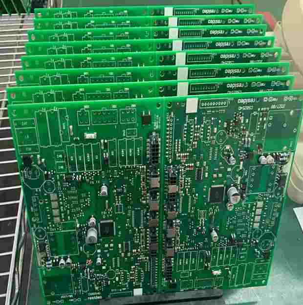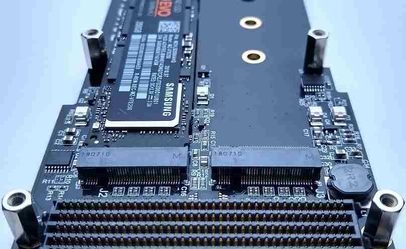
First, use electric soldering iron to weld.
It is best to use a constant temperature electric iron for SMT patch components. If an ordinary electric iron is used, the metal shell of the electric iron should be grounded to prevent induced voltage from damaging the components. Due to the small size of the flake components, the tip of the iron head should be thin, and the cross-sectional area should be smaller than the welding surface. When welding, pay attention to wiping the iron head at any time to keep the iron head clean; Welding time should be short, generally not more than 4s, see the solder begins to melt immediately raise the iron head; During the welding process, the soldering iron head should not touch other components: after the welding is completed, the 2~5 times magnifying glass with a lamp should be used to carefully observe whether the solder joint is firm and whether there is virtual welding phenomenon: if the solder needs to be plated, the soldering iron head should contact the place to be plated for 1s, and then put the solder, and immediately withdraw the electric iron after the solder is melted.
1. SMT patch components at both ends of welding . When welding components at both ends of resistance, capacitor and diode, solder on a pad first; then, press the electric soldering iron on the pad with the right hand to keep the solder in molten state; hold the components with tweezers with the left hand to push them to the pad, weld one end first, and then weld the other end.
Another welding method is to first apply flux on the welding pad, and point a drop of adhesive on the substrate, and then place the components on the predetermined position with tweezers, weld one foot first, and then weld the other pins. When installing electrolytic capacitors, weld the positive electrode first and then the negative electrode to avoid damage to the capacitor.
2. The welding technique of QFP chip is shown in Figure 2. To weld the integrated circuit of QFP package, first place the chip in a predetermined position, weld the 3 pins on the corner of the chip with a small amount of solder (see Figure 2 (a)), so that the chip is fixed accurately, and then evenly coat the other pins with flux and weld them firmly one by one (see Figure 2 (b)). During welding, if solder adhesion occurs between pins, remove the adhesion according to the method (see Figure 2(c)). Apply a small amount of flux to the adhesion and gently scrape along the pin with the tip of the electric iron (see Figure 2 (d)).
Welding SOT transistors or SO or SOL encapsulated integrated circuits is similar. Solder two pins first, then evenly coat the other pins with flux, and solder them one by one.
Two, with hot air table welding.
IC welding can also be done using a hot air table, however, the solder should be solder green, not solder wire. You can first apply solder paste to the pad by manual spot coating. After pasting the components, move quickly around the chip with the hot air nozzle and evenly heat all the pin pad to complete the welding.
If, when welding with electric iron, some pin bridging short circuit or welding quality is not good, you can also use hot air table for dressing. Drip-coated no-cleaning flux is applied to the pad, and then the solder joint is heated by hot air to melt the solder joint. The short circuit spot is separated under the action of the flux to make the surface of the solder joint bright and round.
Note the following points when using a heat gun.
1. The air nozzle should be 1~2mm away from the solder joint to be welded or removed. It can not directly contact the pin of the component, nor is it too far away, and it should be stable.
2. When welding or removing components, do not blow hot air continuously for more than 20s once, and do not use hot air in the same position for more than three times.
3. For different welding or dismantling objects, the appropriate temperature and air volume Settings can be optimized by referring to the temperature curve provided by the equipment manufacturer through repeated trials.

2. Control methods for temperature and humidity sensitive elements in SMT processing plants
In order to ensure the proper use of temperature and humidity sensitive components during SMT patch processing and prevent the use of anti-static packaging materials due to the environmental moisture, humidity and influence of SMT patch components, the following points can be effectively managed and controlled to avoid the quality of materials affected by improper control.
I. Environmental control.
The ambient temperature of the workshop where temperature and humidity sensors are used is 18~28℃, and the relative humidity is between 40% and 60%; Relative humidity of moisture-proof box during storage 10%, the temperature is between 18~28℃; The material clerk shall check the temperature and humidity of the moisture-proof box every 4 hours and record the temperature and humidity value in the Temperature and Humidity Control Table. If the temperature and humidity exceed the specified range, immediately notify relevant personnel to improve and take remedial measures (such as placing desiccant, adjusting indoor temperature, or taking out components from the faulty moisture-proof box and placing them in a qualified moisture-proof box). The open time or open time of the temperature and humidity environment space in each closed area shall not exceed 5 minutes to ensure that the temperature and humidity conditions can be kept within the control range.
Two, process control.
1. When removing the vacuum package of humidity sensitive components on the smt patch line, you must wear electrostatic bracelets and gloves and open the vacuum package on a well-protected tabletop. After being disassembled, check whether the humidity card changes according to the requirements on the label on the package bag. For smt patch IC conforming to the requirements, attach "Humidity Sensitive Element Control Label" on its packaging.
2. When the production line receives bulk humidity sensitive components, it shall confirm whether the components are qualified according to the "Humidity Sensitive Components Control Label", and give priority to the qualified components.
3. Humidity sensor (IC) after vacuum packaging, before backwelding in the air exposure time shall not exceed the humidity sensor grade and life.
4. For the IC that needs to be baked and unqualified, it shall be handed over to the quality control personnel for rejection processing and returned to the warehouse.
Third, control method
1. Feeding inspection - moisture-proof bag should be attached with desiccants, relative humidity card, moisture-proof bag should be standardized outside the relevant text warning slogans. If the packaging is not good, it needs to be confirmed by relevant personnel.
2. Material storage -- unopened materials are stored according to the instructions; If the opening materials need to be returned to the warehouse for storage, they shall be vacuumized and sealed in moisture-proof bags after baking. If the opening material is not used immediately, store it in a low temperature oven.
3. On-line operation -- unpack when in use, and check and fill in the humidity indicator card; Fill in the refueling control card and indicate the symbol of temperature and humidity sensitive element; After dehumidification according to storage regulations, returned materials shall be packed and stored according to corresponding requirements.
4. Dehumidification operation - Select baking conditions and time according to the humidity level of smt patch components, environmental conditions and opening time
3. The safety measures of manual welding are analyzed
Generally, manual welding is the most common in smt processing, but some safety measures should be paid attention to in the welding process, so as to work more efficiently. Smt welding needs to pay attention to the following safety measures.
1, because the distance from the electric iron head 20~30cm concentration of chemical substances is much smaller than the recommended value, so welding should maintain the correct operating position, the top of the electric iron head from the operator's nose tip to maintain at least 20cm above, to work to straighten the waist, sit upright, do not bow down operation.
2, lead almost does not evaporate, but because of the operation to pinch the solder wire with the thumb and forefinger, the fine powder of the filler metal will adhere to the fingertips, so we must develop the habit of washing hands before meals.
3. When smt is processed and welded with automatic welding machine, a large amount of smoke generated by the welding machine covers the room. At this time, you can first open the air device, and then begin to operate.
4. When smt is processed for welding, especially when the welded wire needs to be removed for repair, sometimes the solder will break out due to the elastic action of the wire. Bouncing needles can cause accidental injury, so wear protective glasses when handling them. This must be enforced firmly.
5. There shall be no splashing filler metal on the workbench and the surrounding ground to prevent the filler metal from adhering to the body or clothes. Clean at least once a day so that welding can be performed in a clean environment.
6, because there are many times when the soldering flux or solvent is used, and the electric iron is placed on the work table. From the point of view of fire prevention, it must be equipped with the electric iron frame, the electric iron should be neatly placed, so as to be orderly.
7, some people often stick to the excess filler metal on the electric iron down, which is not only easy to hurt others, but also dirty the ground. Therefore, the electric iron rack can be placed on the electric iron head cleaner for scrubbing. Or place a wet towel on the operating table, which can also be used to wipe the solder off the iron.
8. In addition, when welding in dry seasons, you can wear anti-static bracelets and anti-static work clothes.


