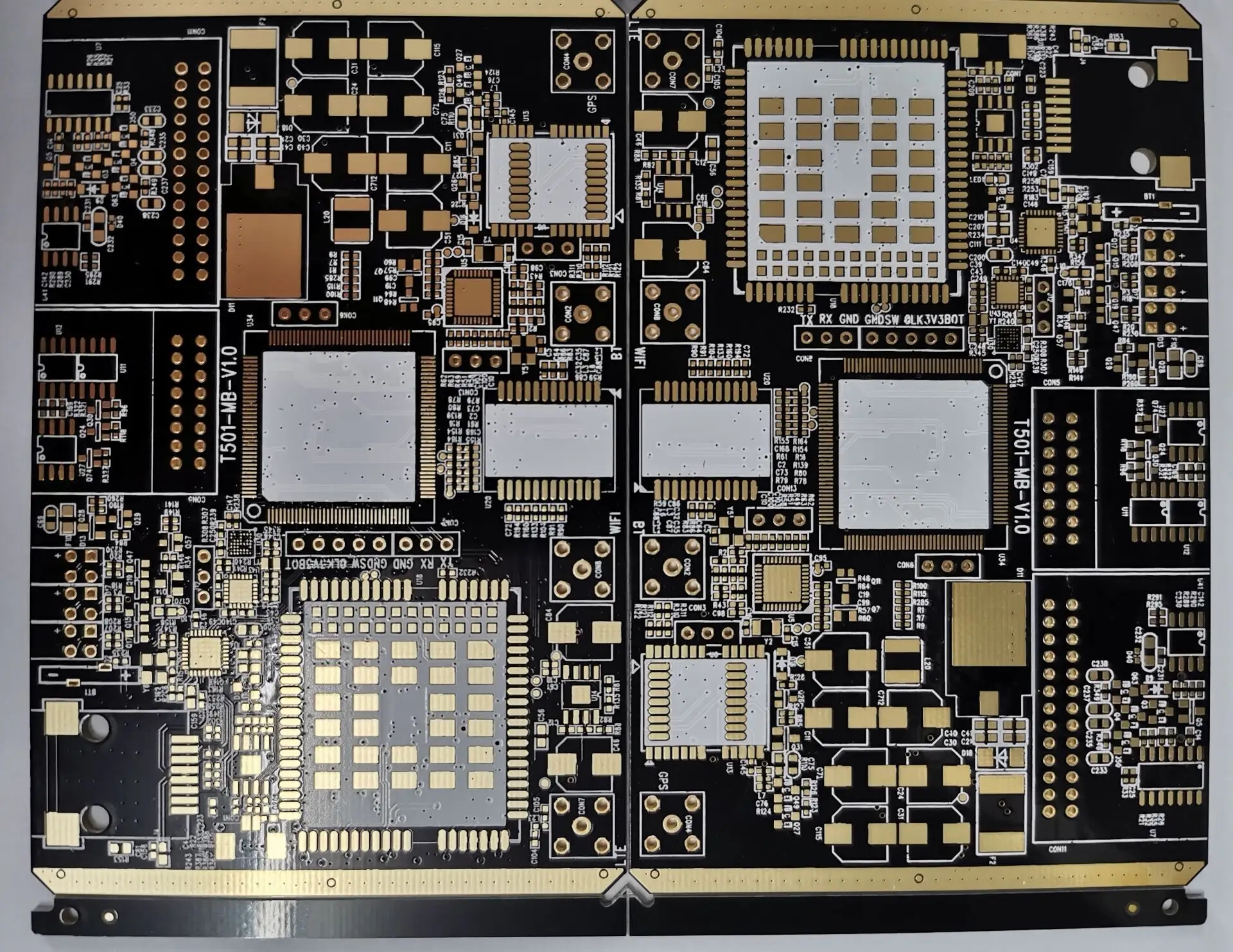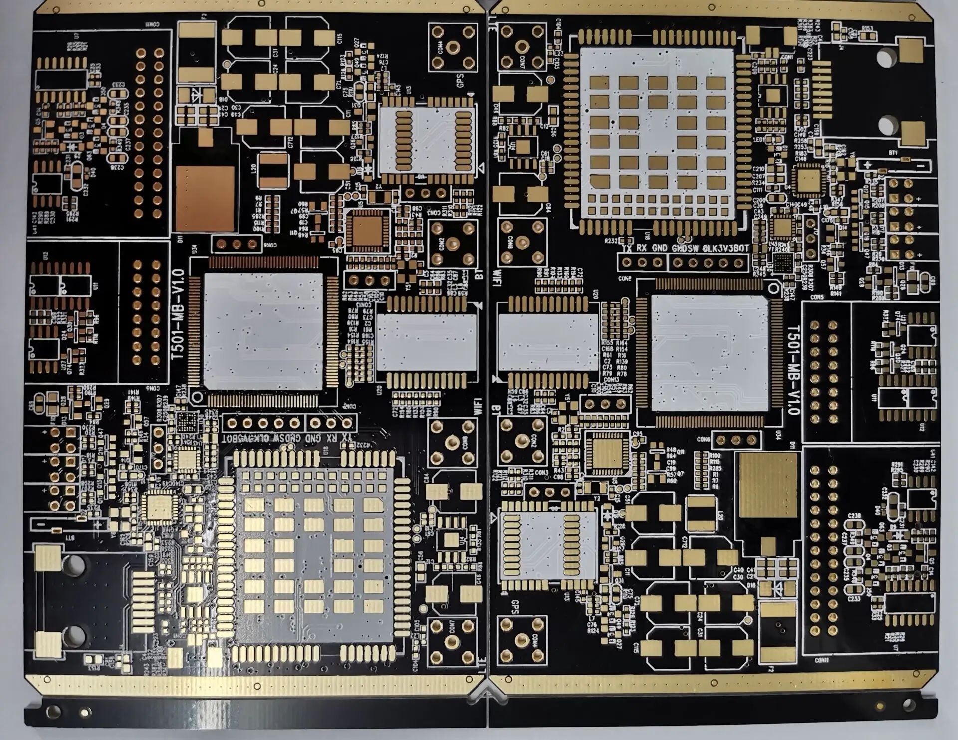
Introduction to Hole Plug Hole Technology in PCB Fabrication Disk
circuit board manufacturing, circuit board design, PCBA processing manufacturer will explain the technology introduction of the hole plug hole in the circuit board manufacturing tray
1、 Preface
With the development of electronic products in the direction of light, thin and small, PCB has also been pushed to the development of high density and high difficulty, and the requirements of customers are also getting higher and higher. Some customers also require a plug hole for the hole in the plate, so the requirements for the plug hole are getting higher and higher. For example, no solder blocking ink is allowed to enter the hole, which causes tin beads hidden in the hole, no oil explosion, and makes it difficult to mount the mounted components
As we all know, the plug hole procedure of PCB is a process arising from the higher requirements of PCB manufacturing process and surface mounting technology. Its plug hole functions are as follows:
Prevent short circuit caused by tin penetrating the component surface from the through hole during PCB over wave soldering
• Avoid flux residues in the through hole
• Prevent solder beads from popping up during wave soldering, causing short circuit
• Prevent the solder paste on the surface from flowing into the hole, causing false soldering and affecting the mounting
The most difficult thing to control for the hole plug hole in the plate is that there is tin bead or ink upper pad in the hole, which is the so-called oil explosion phenomenon. Some customers of our company have very strict requirements for the solder mask upper pad and its appearance. Among them, the production plate requires the hole plug hole in the plate. The most difficult thing to control when we produced this plate before is the oil explosion problem after curing or tin spraying, which leads to the solder mask upper pad and tin bead in the hole. Curing or tin spraying is a process of solvent volatilization and resin shrinkage of the hole stopper ink. Therefore, improper control is most likely to cause tin bead or oil explosion in the hole

2、 Test
Test 1. Straight plug method
Drill the aluminum sheet with the hole to be plugged. The size of the aluminum sheet is 2 inches larger than that of the processing plate, and the hole diameter is greater than 0.1MM than that of the actual processing plate. Make a screen plate or directly install it on the screen printing machine for plug hole. After the plug hole is completed, stop it for no more than 30 minutes. Use 36T screen to directly solder the screen printing plate surface. The process flow is as follows:
Pretreatment - plug hole - silk screen - pre drying - exposure - development - curing
With this process, the production cycle can be relatively short, and the conductive hole cover oil is good, the plug hole is flat, and the wet film color is consistent. After the hot air leveling, the conductive hole can be guaranteed not to be coated with tin, and no tin beads are hidden in the hole. However, in the requirements for the hole plug hole in the plate, its position is easy to cause curing or oil explosion after the hot air leveling, and the ink in the hole is used to solder the plate, resulting in poor solderability.
Test II. Grinding method
Drill the aluminum sheet with the hole to be plugged. The size of the aluminum sheet is 2 inches larger than that of the processing plate, and the hole diameter is greater than 0.1MM than that of the actual processing plate. The screen plate is made or directly installed on the screen printing machine for plug hole. The plug hole must be full, and the two sides are preferred to protrude. After curing and polishing, the plate surface shall be treated. The process flow is as follows:
Pretreatment -- Plug hole -- Precuring -- Grinding -- Pretreatment -- Print resistance welding
As this process adopts the plug hole curing, it can ensure that the oil will not fall off or explode after HAL, but after HAL, it is difficult to completely solve the problem of tin coating on the through hole tin bead and through hole, and the production cycle is long
Tin bead for hole in plate
The hole plug and hole plate in the production plate were welded to the upper pad or the tin bead in the hole due to oil explosion in the hole in the plate, resulting in a large number of rework and scrap. After some process parameters were changed, this problem was obviously controlled
Test 3: subsection pre drying method (we modify the process based on Test 1)
Tool preparation
a. Plug hole aluminum plate: the size of aluminum plate is 2 inches larger than that of processing plate, and the hole diameter is greater than 0.1mm than that of actual processing plate
b. Fabrication of base plate: drill a base plate with the same thickness as the through hole, and the plate thickness can be 1.0 to 1.6mm. The base plate is good for preventing holes when plugging holes and preventing ink in the through hole from polluting the table surface. This base plate is more suitable for the plug hole plate with a thickness of more than 1.6mm
Production process:
Brush plate ---- nail bed fabrication ---- plug hole (determine which side to plug according to the customer's requirements) ---- print resistance welding ----- pre drying ----- exposure ----- development ----- sectional curing
Specific process and description:
Fabrication of nail bed
Prepare an etched base plate as the nail bed. The plate thickness is 1.6, and the size is more than 10cm larger than the four sides of the plug hole plate. Then use 1.6mm thick and 5cm wide copper strips around the nail bed to support the plate surface with the nail bed according to the size of the plate, so that the force is uniform
location
After the nailing bed is fixed on the fingerprint table, the board of the fort is positioned on the nailing bed with rivets.
Precautions: 1. When the plug hole plate is positioned on the nail bed, the copper strips on the four sides of the nail bed shall not exceed the figure area
2. The bed nail must be positioned outside the forming area or on the base material,
Screen making
Take out the aluminum sheet of the plug hole to distinguish the CS and SS surfaces, align the locating hole on the plate with the locating hole on the aluminum sheet, fix the aluminum sheet of the plug hole on the back of the 36-34T blank mesh with tape, and then conduct the plug hole
Plug holes from the component surface (unless otherwise required by the customer), first make a first plate, check whether the plug holes are aligned, and then start continuous production after proper adjustment; The production process requires strict self inspection and self-control, and timely adjustment in case of deviation. The ink in the plate hole after the plug hole must be full, and oil leakage can be seen on the reverse side.
Precautions: 1. The bed nail must be positioned outside the forming area or on the base material,
2. Pay attention to the scratch of bed nails on the upper and lower plates.
Print resistance welding:
Fix the nail bed used for the original plug hole on another fingerprint table, select the mesh and stop point according to the requirements, and then print the solder mask normally. After printing the first side, print the second side.
Precautions: 1. The bed nail must be positioned outside the forming area or on the base material,
2. Pay attention to the scratch of bed nails on the upper and lower plates.
Pre drying: 72 ℃ for 45 minutes
Exposure: normal exposure (9-11 levels)
Development: normal development
Staged curing: first stage: 80 ℃ for 40 minutes
The second section: 100 ℃ for 40 minutes
The third section: 120 ℃ for 40 minutes
Section IV: 150 ℃ for 60 minutes
Note: Sectional curing is the most important, and the pre drying and curing time must be guaranteed
3、 Conclusion
5.1 From the above results, it can be seen that the ink solvent volatilization and resin shrinkage during curing or tin spraying have been well controlled by using the segmented pre drying method after the stopper hole
5.2 The plug hole is also an important procedure in the printed circuit board. The quality of the plug hole also affects the mounting of the components of the printed circuit board and causes other quality problems. With the increasing requirements of customers for the plug hole, how to ensure the quality of the plug hole? In a word, the adopted process method must be combined with the actual design, and the process flow and parameters must be strictly controlled to ensure the good operation of the process and further improve it. The Circuit board manufacturer, circuit board designer, and PCBA processor will explain the hole plug hole technology in the circuit board manufacturing panel.


